|
Projects | Guides | Gallery | Articles | Contact |

|
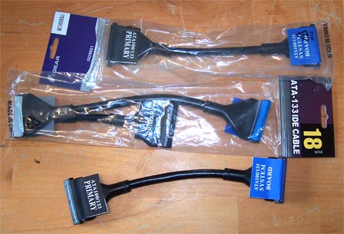
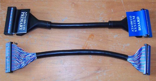
Work Log Page: [1] - [2] - [3] - [4] - [5] - [6] Time to Crack the Whip... Update 06/26/2006 The flat ribbon IDE cables I had intended using looked unsightly inside the case and covered up too much of the motherboard. There was no good way to fold them out of the way so I scrapped them in favor of the black rounded IDE cables shown below. I removed the paper tabs and the boots from the ends
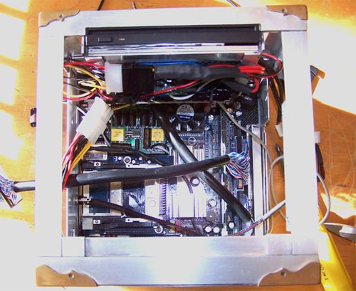
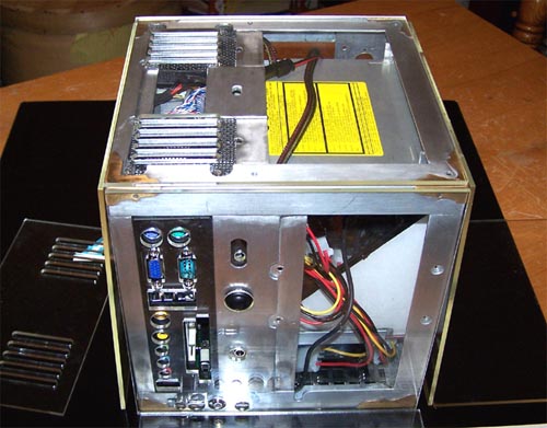
Here are the cables attached to the main board and positioned within the case, it looks much nicer without the fat black IDE cables covering up all the hardware.
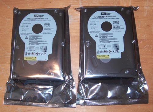
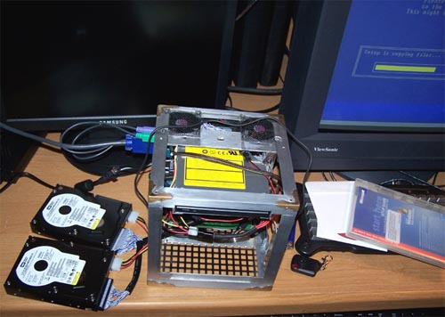
Next up are the two 320GB hard drives that will replace the two 250GB drives that I had originally planned on using... 640 GB, beefy!
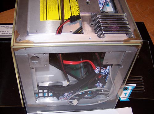
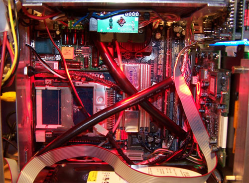
Below are the two drives hooked up to the main board and Windows Media Center being installed, it is now officially a computer. I still have some hardware to install - pinhole camera, LCD screen and Matrix Orbital - and the hard drives still need to be mounted but it is definitely working, so I am working on it again.
Yesterday I went and saw my friend with the laser, we worked together all afternoon cutting the pieces of Acrylic that will make up the case exterior, he also has a really cool, brand new, high end industrial printer... if I would have measured out the parts placement beforehand he could have back painted the panels too. I don't know how well it would have worked because I don't want the light to show and I am uncertain of the inks opacity, but like he said... it could also just print out a painting template directly onto the acrylic to make masking easier.
Check out the tasty laser-y goodness... Mmmmm, crunchy. The picture below shows the laser vented top panel and the front illusion section panel with the slot for the DVD burner cut out, it's starting to come together.
Below is the side panel that everything hooks into and ports out of, it came out really kick ass... especially when you factor in how it was done. The case was placed onto a flatbed scanner (connector side down) and the scanned image was then traced in Corel Draw and used as a cutting template.
The following picture shows just how well everything lines up, it only took two tries cutting scrap to get it all lined up perfectly... sweet.
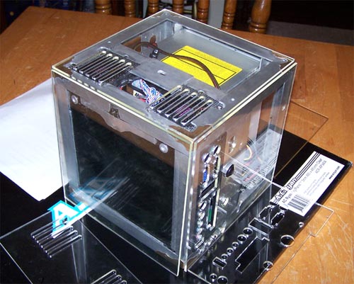
Three-quarter overhead view of the mother board tray side, the port out side and top...
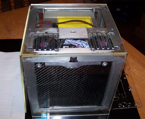
Motherboard side and top... the vent slots on the top panel turned out awesome and everything fits together really nicely.
Lastly, the LCD and Matrix Orbital side panel.... no real fancy laser cutting on this or the last panel other than being cut to size.
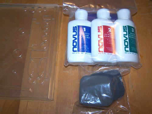
The acrylic panels have a few minor defects here and there, I am detail crazy (anal) and now currently working on polishing out all the tiny scratches, swirl marks and laser haze. Quality of work over quantity of work, with modding (or art) if there is anything that I can do to make it better I will likely end up doing it... so panel polishing, though tedious and in no way fun, was necessary and will make the finished mod that much better. The picture below shows the three different bottles of Novus and below them the sanding pads that came in the $14 sample kit I bought, I don't need to use the sanding pads as none of the scratches are deep (thankfully).
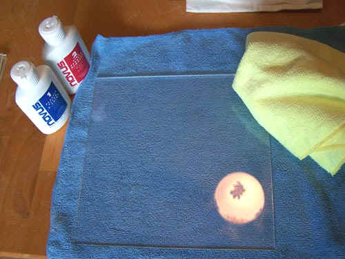
The scratches and such are minor enough that I skipped using Novus #3 altogether, here's how it went... clean the panel with Novus #1, then polish it with Novus #2 and then clean it again with Novus #1, check your work and then repeat the entire twenty minute process. I have somewhat mixed feelings about Novus, it works and all that but then again so does toothpaste and Brasso... oh well, the sanding pads are nice.
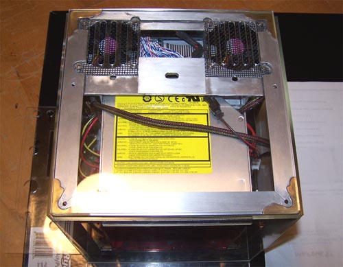
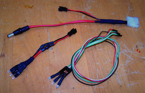
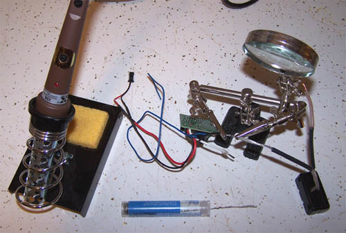
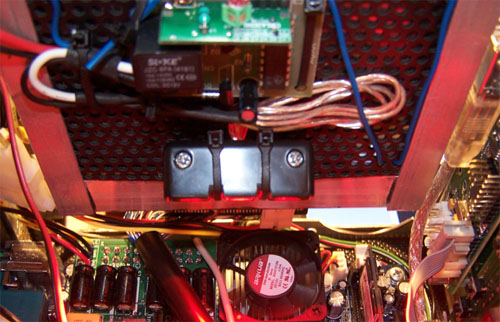
Today I worked on the wiring, I had to before I could do anything else because with everything hooked up to the little PSU... the remote control 40 LED lighting I made would not work, it does however work when connected to my test PSU. I think that I may have been splitting the power off too many times, the top cable in the picture below should fix the problem - I eliminated the power lead for the back case lighting so it now only has to power the remote lighting and pinhole camera. The old three LED array in the lower left of the picture below will not be used in the mod now (since it's power lead was eliminated) so I instead made a new three LED array that will not only light the back panel of the case but also serve a higher purpose by connecting to the main board as the power on, HDD activity and suspend LED's.
The rounded IDE cable that I intended to use for the HDD's is dead, I was using a pair of electricians scissors to remove the black tubing from the cable in between the drives and wound up slicing through two of the wires. I ordered two more 18" dual device black rounded IDE cables so I can try it again, hopefully they get here soon. I spent some time working on the graphic for the carbon fiber side panel, I think it came out pretty decent. The inner lettering that is white will be masked off from the inside of the panel and will not be vinyl dyed, when combined with the LED back lighting and carbon fiber it should look pretty cool.
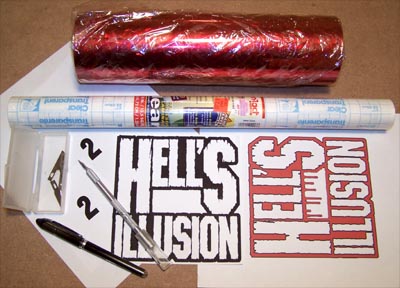
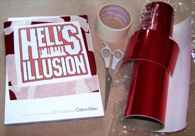
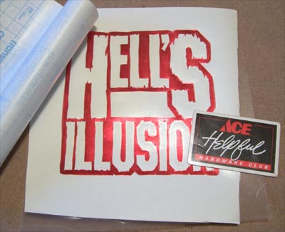
Below shows the red mirror chrome vinyl stock, a roll of transparent contact paper, ball point pen, an X-Acto knife and the decal design printouts.
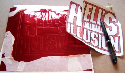
The following picture shows the pattern taped onto a cut piece of vinyl stock and the whole shebang taped to a magazine.
The outline of the pattern was traced with a ballpoint pen ( the magazine beneath provides a little give so that the impression is deeper) the pattern sheet was then removed - the picture below shows the impression lines.
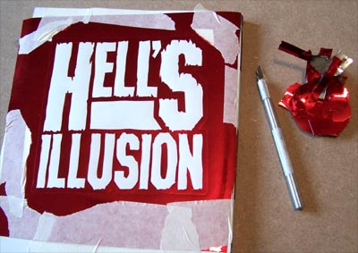
Using an X-Acto knife with a fresh blade I began the task of cutting the vinyl, the trick here is to apply just enough knife pressure to cut through the vinyl but not go all the way through the paper backing. After cutting for a few minutes you will be able to tell by how the cut sounds if you are going too deep.
Be careful when removing the scrap vinyl, watch that you don't let the piece you are removing get stuck to the decal, this can happen when cut lines don't meet up since you have to hit it again with the knife, when you peel sections up always pay attention to what the scrap material is doing.
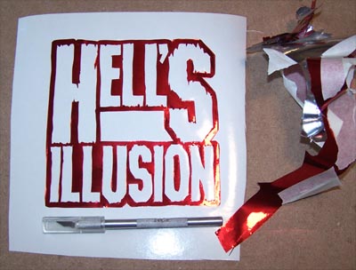
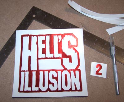
With all the scrap material removed a piece of clear contact paper is cut and than applied to the decal using a credit card.
Below shows the decal coated with contact paper, cut to size and ready for install.
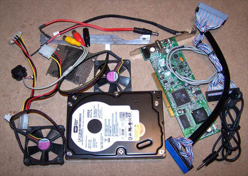
After thinking over the past couple months about this mod I decided there was a need to simple things up and there are a few reasons why. I planned the internal part of this mod really well, but had no plan for attaching the outer acrylic panels... the method I have come up with does not allow for the side mounted hard drive since it attaches directly to the corner angle. The hard drive that was removed would have had questionable ventilation to it's underside anyway, with a single drive mounted to the openly vented case bottom the top fans become unnecessary... color them gone. I wanted to lighten the load to the power supply so that the 6" LCD could lose the external 12V power adapter and run PSU direct, so the HDD, both fans, the pinhole camera (a novelty that would have been lost in a sea of novelty) and the TV tuner card + IR receiver (piece of crunk) have all been removed.
With all the above parts removed I once again fired up the little computer, plugged in the 6" LCD monitor and set it up in the BIOS. Next, I installed Windows and all the drivers and the small LCD worked perfectly through it all powered by the tiny PSU... right as I was about to give myself a pat on the back I remembered that I had not tested the remote control lighting. I grabbed the remote and pressed the on switch... the PC powered off... not good. I tried it a couple more times before deciding that 40 LED's might have been a bit overkill to begin with, two Lazer LED's are not as bright or impressive as the LED array I built, but is more realistic.
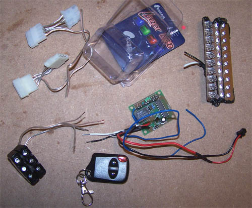
In the top right of the above picture is the homebrewed LED lighting that was removed from the remote sensor and the bottom left shows the Lazer LED's that will replace it. I screwed together and notched the edges of the Lazer LED's so that the zip ties don't move around and two rubber grommets were used to spread them apart to space out the lighting. Below shows everything ready for soldering with the heat shrink ready after.
I plugged everything back in to test fire the lighting, the following picture shows the zip tie mounting method for the LED's and remote sensor...
And below is the case interior lit up by the Lazer LED's, not nearly as bright as the 40 high intensity LED's I had intended to use, but still bright enough to light things up.
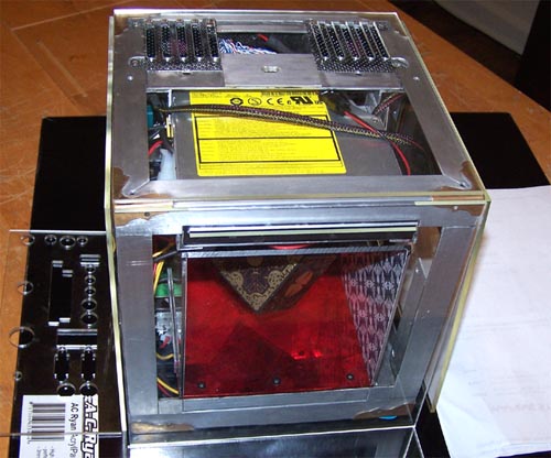
It's alive, working properly and looking very sweet... next up, the money shot. I still have a few things left to do before I begin working on the outer panels, I may in fact wind up entirely re-doing the outer panels. ACRyan AcrylPanel scratches like mad, it's a fairly 'soft' acrylic and not really optimal as an external case surface... so it is at this point up in the air as to whether it will be used for anything other than a template.
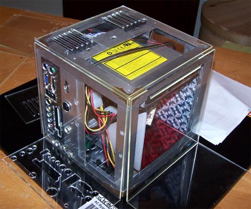
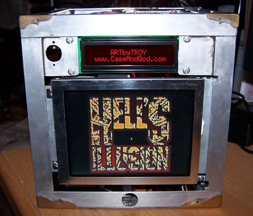
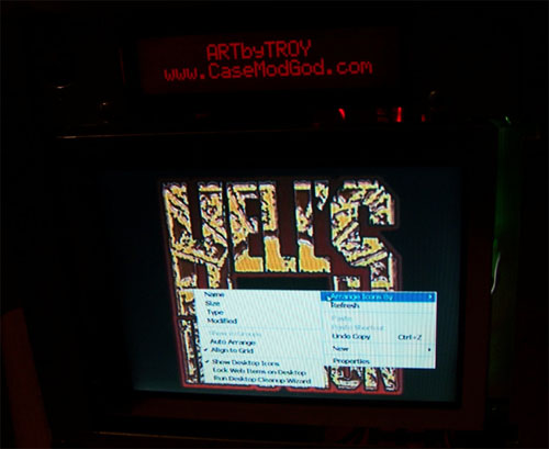
The 6" LCD monitor is a bit clearer in real life than it looks in the following picture, but it does show the tiny monitor with open windows on it doing stuff and/or things. Pretty sweet so far, but I still have not come up with a finalized attachment method for the outer panels... that will be next.
|
|
|