|
Projects | Guides | Gallery | Articles | Contact |

|
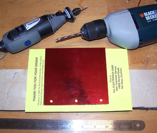
Work Log Page: [1] - [2] - [3] - [4] - [5] - [6] I plan to illuminate the interior of the illusion section using three white 3mm LEDs that will be connected to the LED breakout from the Matrix Orbital display. I drilled three evenly spaced holes into the bottom panel of the illusion section and then used the Dremel with a grinding bit to make the holes large enough to fit some 3mm LED clip holders.
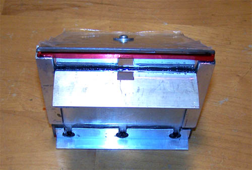
Below shows the illusion section bottom panel with the LED clip holders installed, I also filed down three white LEDs and they are placed into the clip holders to test for fit, the left side of the picture shows the Matrix Orbital LED display... pre-modified.
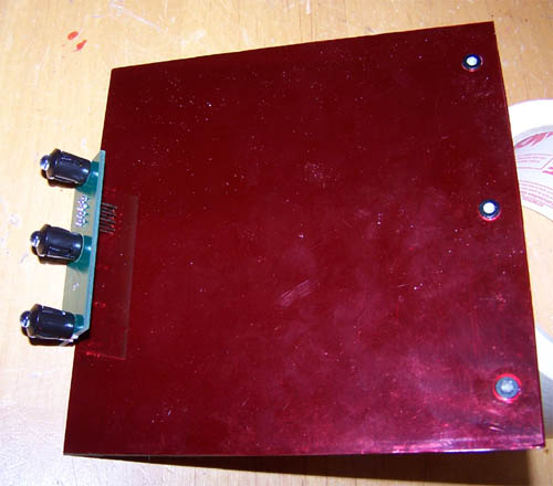
Ok, the idea is to make the illusion section completely removable which means that the LED's and Matrix Orbital breakout PCB will have to be attached directly to it.
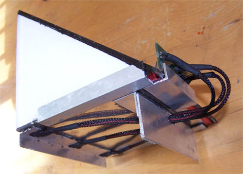
In the pictures above and below you can see the Alum-angle that I cut, nibbled and filed into submission and then JB-welded to the bottom of the illusion section.
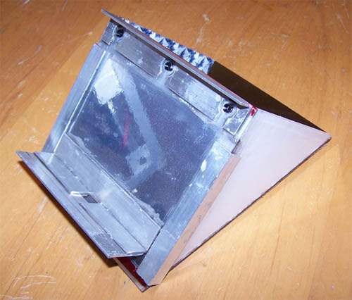
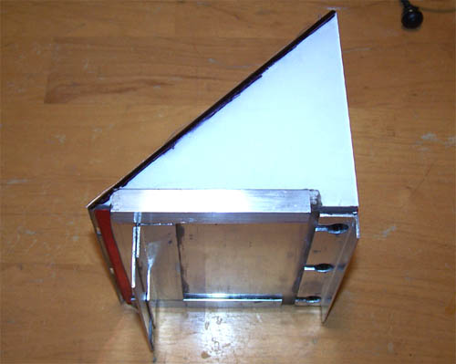
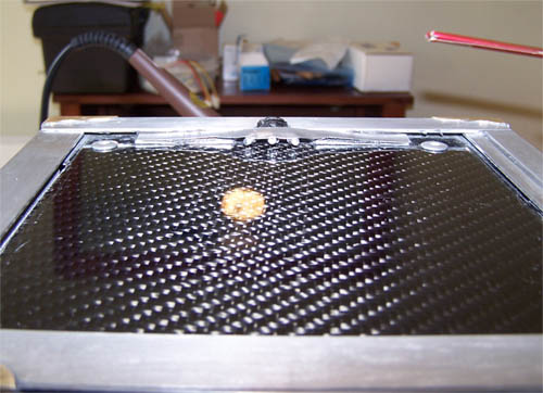
Here is a side shot of the magic, the illusion section will sit directly over the lower hard drive and will lock into place above it... Alum-angle is indispensable, easy to work with and fairly priced stuff, the cuts here were all made with a nibbler and cleaned up with a file.
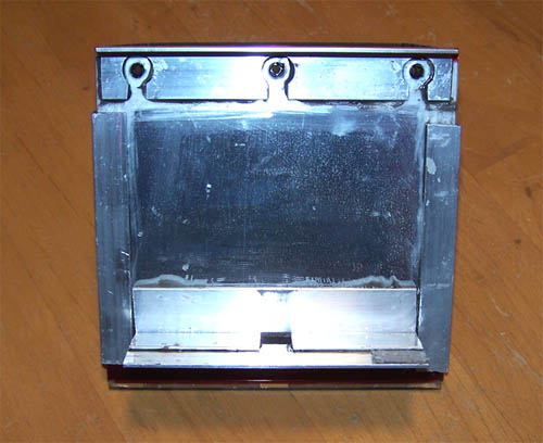
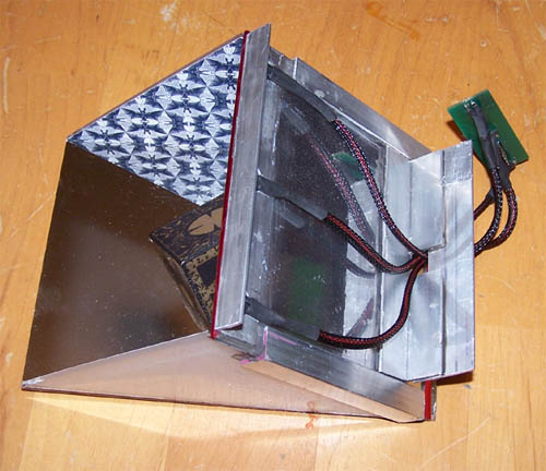
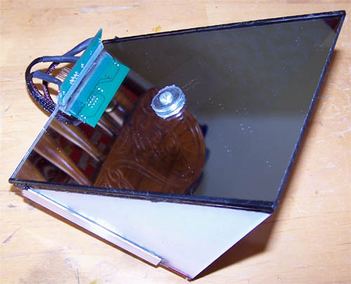
Below is a back down shot that shows the hole I cut in the back to allow for the LED wiring to pass through, and yes the protective film is still on the back of the 2-way mirror.
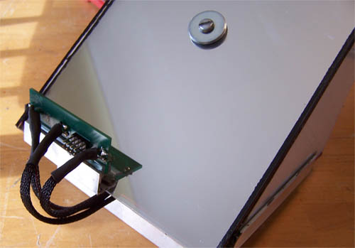
Here is the Matrix Orbital LED PCB all wired up and test fit into place, at this point I'm still thinking out how best to mount the PCB to the illusion section...
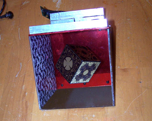
A view of the illusion section upside down with the reflected LED's shown positioned within their clip holders, just throwing it out because it looks so damned cool...
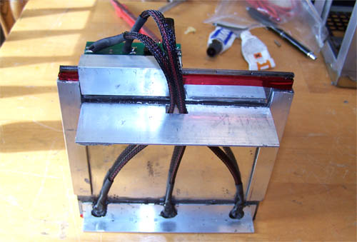
Here is the mounting method I came up with for the Matrix Orbital LED PCB, basically it is a strip of door edge molding that has been JB-welded to a piece of Alum-angle and the PCB sits snugly inside of it.
This next picture might clear up any questions about the mounting method, it clearly shows the short piece of Alum-angle that I used to mount the door edge molding and PCB to as well as the wiring beneath.
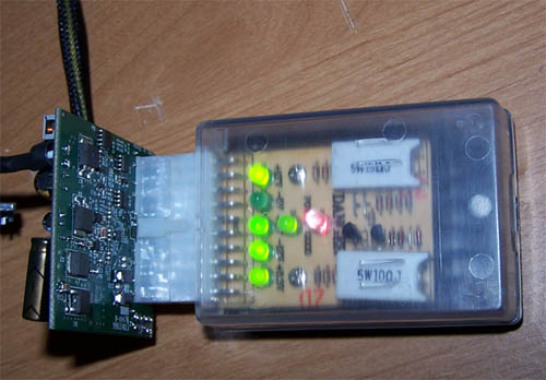
Close up shot of the LED break out, the solder job is entirely newb looking but based on past experience will work. I have a variable temp soldering station on order and it should be here soon... hopefully it will help me solder better ;P.
I used liquid electrical tape to hold the sleeved 3mm LED's in position, this was necessary... otherwise they just kept popping out of the clip holders.
With the illusion section all wired up it is time for the final test fit, I also added a couple of cut pieces of flat Alum-angle to the framework at the bottom to keep the illusion section from moving around and also keep it centered within the mod.
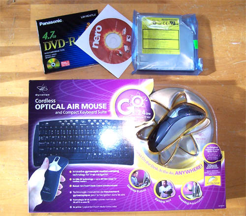
Splurge-thirty PM... Since the mod will for the most part be used as an HTPC the parts below just make sense, on top is the slim line slot load DVD burner that I found online for less than $100 (bargain) and the wireless RF keyboard/air mouse combo I picked up for under $80.
I wired up three 3mm red LED's to illuminate the backside of the carbon fiber motherboard tray, when this side is is entirely finished and the back painted panel is installed the lighting should produce a pretty cool effect.
You can kind of see it in the picture above but the one below shows it better, I installed a piece of aluminum flashing overtop of the 3mm LED's in an effort to make sure that the red lighting will not bleed through the outer black back painted panel. The flashing got the sand and clean treatment and some JB-Quick was used to hold it down, once that was all good and dry a dollop of some liquid electrical tape was used to keep the LED wiring in place.
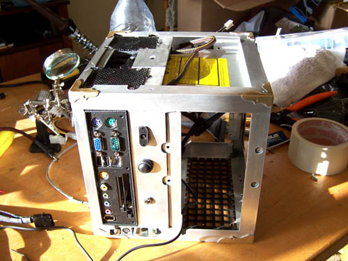
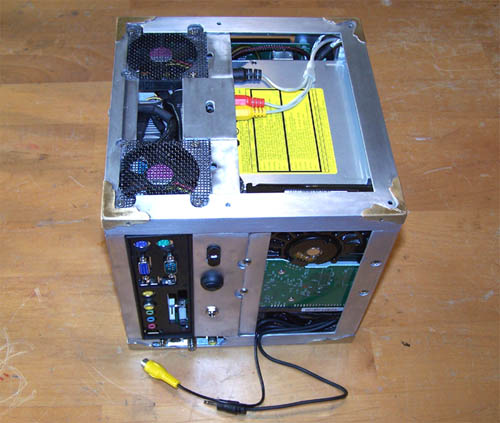
Next up on the agenda is a little cable management for the mini PSU... lol, get it? A "little" cable management... the PSU is little. Whatever, I don't want to bore you with every little detail of the hardware install so instead I will hit you with highlights and mainly show pictures. Below is the true back side of the mod, it is where everything ports out... the vacant space on the right is reserved for a WD 250GB hard drive.
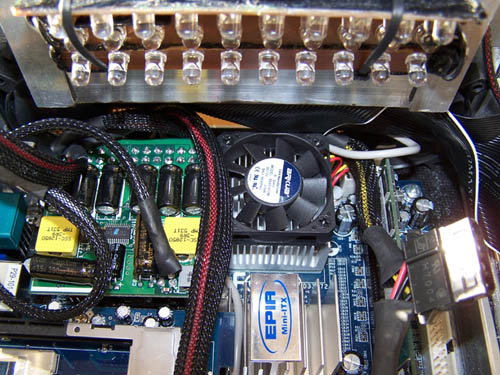
Below shows the damned processor fan, you have no idea how tight everything is just above the processor heat sink... the CD-ROM power cable, IDE cable, sound cable and the sleeved 3 LED assembly I wired up all sit over the processor. The picture below shows my "1337 Jedi oRiGaMi SkillZ", it was an hour long pain in the ass getting everything folded up and out of the way of the processor fan.
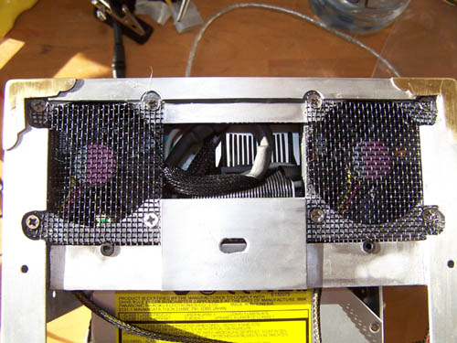
Even though you probably didn't read the above spiel about my cable ordeal, here is a shot from the top showing the cables situated tightly above the processor heat sink.
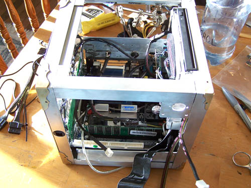
Here's a sloppy looking shot from the monitor side of the cube, I will install the LCD, Matrix Orbital and pinhole camera shortly, the IR receiver however is final installed.
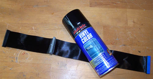
I had a black CD-ROM IDE cable that was leftover from an ASUS motherboard, it is sticking out in the picture above... I needed a black HDD cable, so with a little masking tape and some Vinyl dye I made one... and it is awesome.
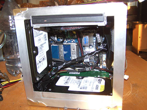
The hard drives are installed and just how tight everything sits together is now made all the more evident, I'm not small at all and it's getting harder and harder to work within the limited confines of the case.
I ain't crying over making things fit, I live for a challenge. Below is a 3/4 shot showing off the freshly installed 250GB hard drives, half terabyte of storage at 8"x8"... cool.
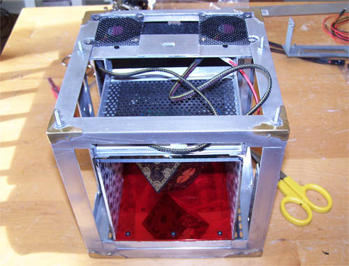
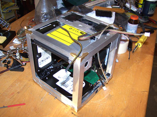
Suck it in fatty! Below shows everything installed and the nightmare of wiring that will need to be reigned in and managed, I hate wire management.
The wiring is at this point still half assed, but I wanted to throw everything in to get a feel for things. Below is the port out side of the mod, the cables at the bottom are for the 6" LCD and the IR receiver.
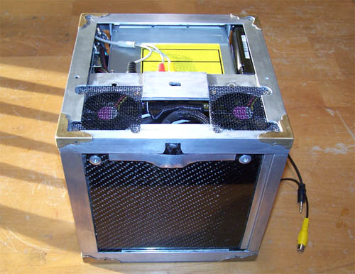
Spinning... 3/4 view of the port side of the mod and the back of the motherboard tray...
Back of the motherboard tray...
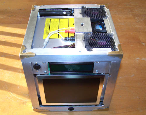
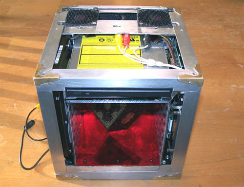
Still spinning... 6" LCD, Matrix Orbital, surveillance camera and IR receiver side...
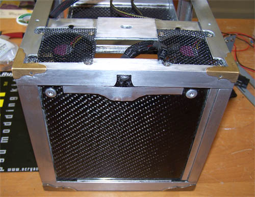
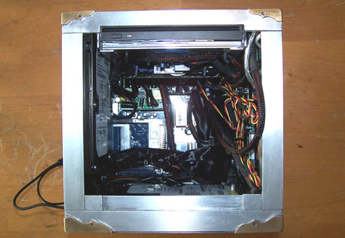
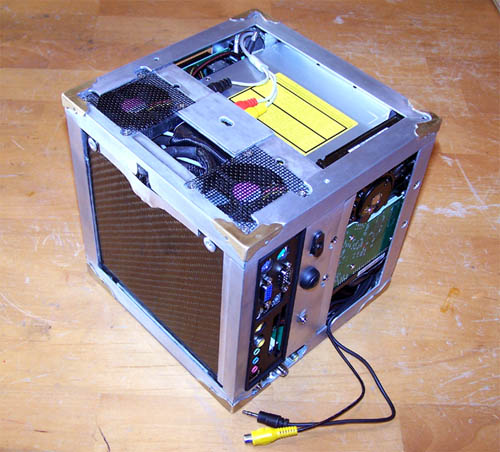
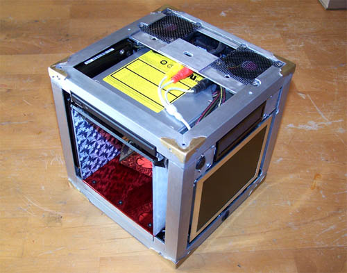
3/4 shot showing the screen side and the illusion section/DVD burner side...
Finally a shot of the illusion section in place, I will work on the wiring a bit more tomorrow and hopefully fire it up after and install Windows MCE... WooHoo!
It's entirely disassembled now... there is
an issue. The PSU I modded up is faulty, maybe I caused it by adding leads to it...
maybe it was fried from the beginning, either way I should have put it on the
PSU tester as soon as I got it because I am having a hard time seeing an RMA
come my way for it now. Nevertheless, I just finished typing an email to the
manufacturer and explained what I did, requested an RMA, sent the email to them
and then promptly ordered another PW200M PSU because the magic 8-ball predicts
my weak ass RMA request most assuredly will be denied.
The power supply problem is now fixed, basically it was my problem and here is how it was explained to me by the manufacturer... "Dear Sir, Good enough for me, now on with it. |
|
|