|
Projects | Guides | Gallery | Articles | Contact |

|
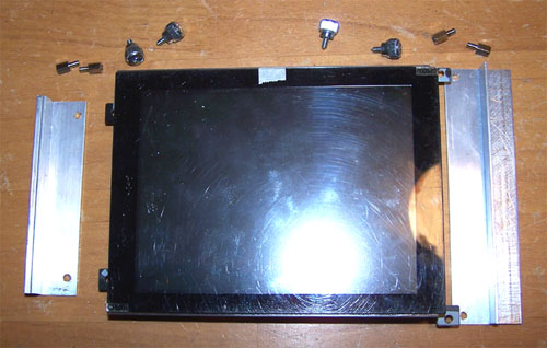
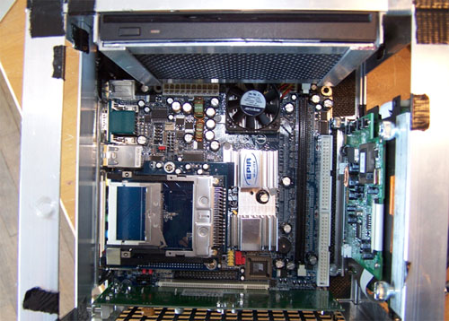
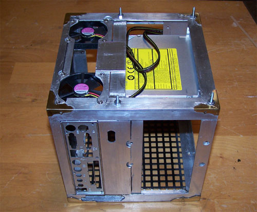
Work Log Page: [1] - [2] - [3] - [4] - [5] - [6] I worked on the project for a few hours today, hands on assembly revealed a design flaw and the side mounted HDD now sits vertically as a result... this also affected the placement of the fans since there is no longer room on the side to mount them with the hard drive positioned this way. The illusion section sits above the HDD with the MB tray showing in the back.
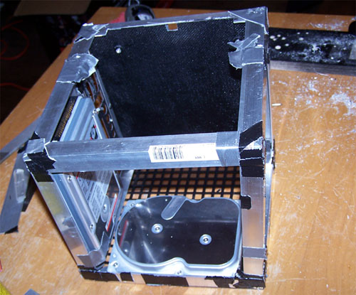
Below shows the hard drive in its new position and the motherboard plate, I placed the illusion section inside the mod to get a feel for the parts placement.
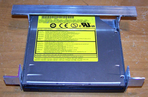
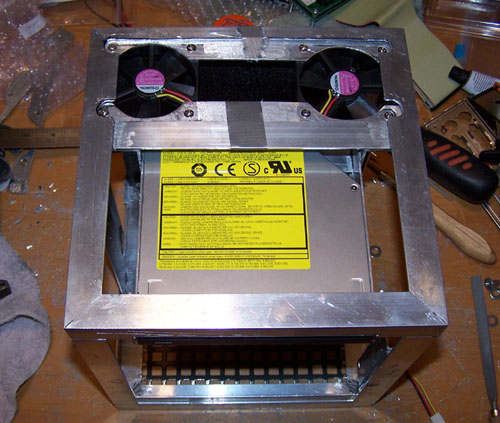
Money shot... the slim line CDRW/DVD drive that is sitting atop the mod in the picture below will actually be mounted in its new location just above the illusion section and below the Alum-Angle front edge.
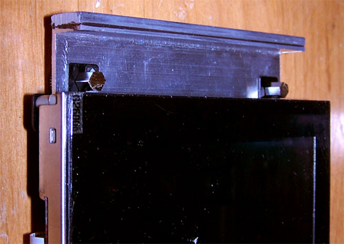
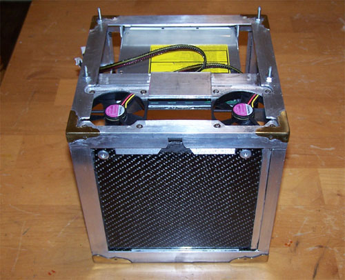
This is the side where the 6" LCD and Matrix Orbital will be located, designing the Alum-Angle framework for this mod is not easy, it is a puzzle in itself and the pieces being fit together do not exist until I make them... I am not complaining as I enjoy the challenge.
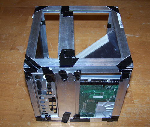
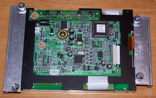
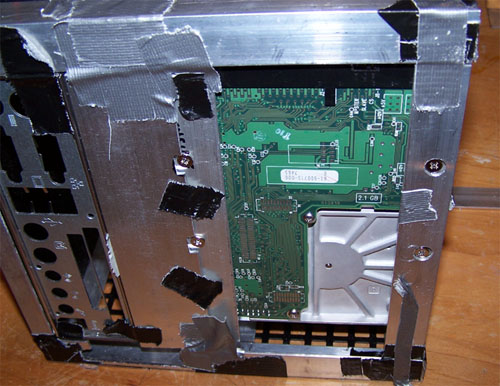
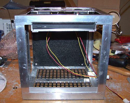
A shot of the backside showing the position of the MB tray, the top notch will be used to wire lighting behind the mother board tray. So far this whole thing is being held together entirely by Duct tape, I bought some J-B Quick and will set to removing the tape and making it all permanent as soon as I am done marking and cutting the Alum pieces that need it.
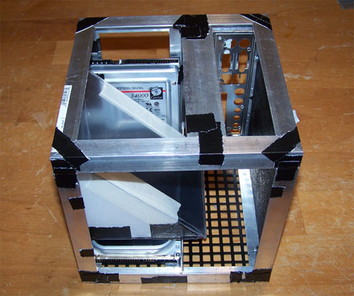
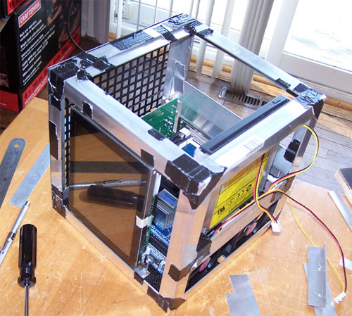
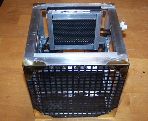
Below is just to show positioning, the CDRW/DVD drive and 60mm fans will be positioned exactly below their current placement, moving the fans fron the side to the top makes better sense anyway since they will be located where they can best remove heat from the side HDD and 6" LCD.
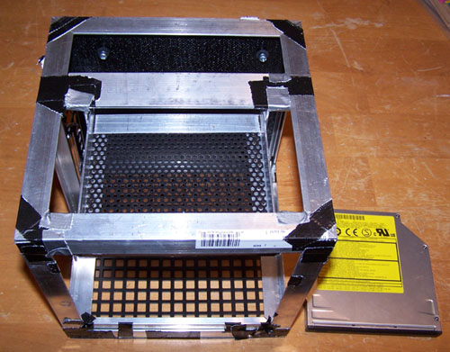
So here's where I'm at, I will be building a cube framework around the illusion section that will also house the CDRW/DVD drive, it will need to be removeable in one piece to allow access to the mother board and rear of the 6" LCD... as always, I have a plan. I also need to frame out the 6" LCD/Matrix Orbital side with some Alum-Angle and figure out final positioning.
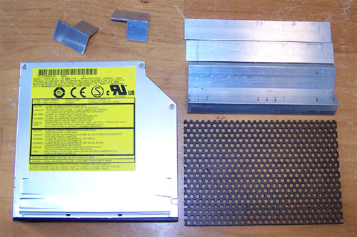
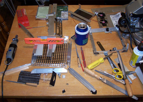
I bought all those big cool table top tools and they rock, but sometimes you need to kick it old school and when that happens you break out the nibbler, Dremel and file. Back to basics, because there is no good way to mount a slim line slot load CDRW/DVD into a custom mod... there, I said it. I used the same drive in my last mod and there was no good way to mount it then, nothing has changed.
I decided to make a tray for the drive, my first design involved J-B Welding stuff onto the drive and I might want to upgrade to a slim slot load DVD burner later so that wouldn't work. Below are the cut pieces of Alum-Angle for the tray, I also cut a piece of some plastic mesh I had laying around for the middle section to allow air in and also because it looks neat.
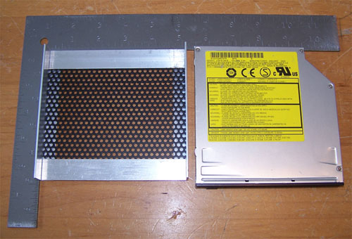
I tested the tray against a forty-five degree angle ruler in preperation for J-B'ing it all together.
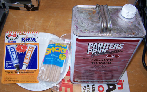
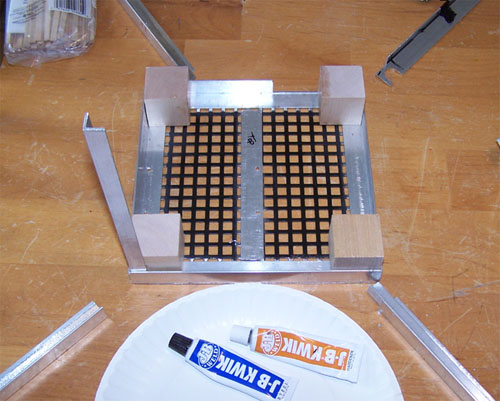
J-B Quick, Skinny Sticks and lacquer thinner... sounds like a party.
The connecting edges of the Alum-Angle CD tray were coarse sanded and cleaned with laquer thinner, the J-B Quick was mixed and applied to hold it all together.
J-B quick is freaking awesome, strong stuff and building the CD tray with it was the true test for the rest. Hand pressure is enough to make the J-B hold, no need for clamps and it is set in four minutes.
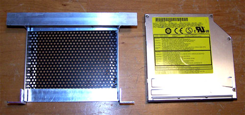
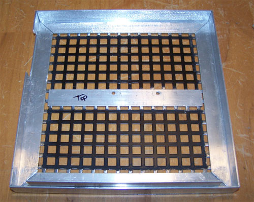
Below is the finished CD tray duct taped into place within the mod, everything lines up and fits perfectly.
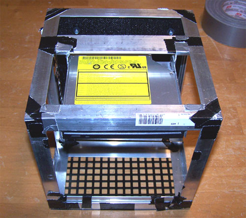
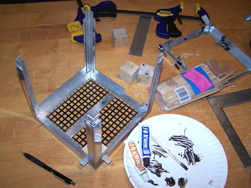
And finally a test fit of the drive, it fits sweet. Designing the CD tray has been a three day ordeal consisting of a lot of head scratching, parts cutting and rethinking, I'm glad it's over.
With the CD-ROM tray finished it is off to another side of the cube, this time we will concentrate on the LCD and Matrix Orbital side, figuring out how to mount these components was a lot easier that the slim CDRD/DVD, below shows the test fit.
The parts fit to size and ready for some J-B Quick...
Here is the final design for the mounting of the 6" LCD screen, I used thumbscrews because they fit in and look killer.
The thumbscrews fit into some shiny steel standoffs that have had the screw section removed with the Dremel. There is still a small amount of cutting to do but I plan to J-B the whole shebang together by the end of this week.
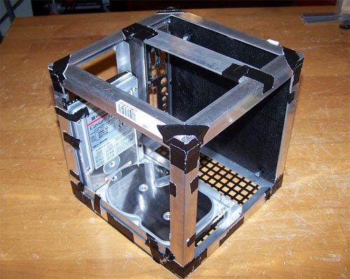
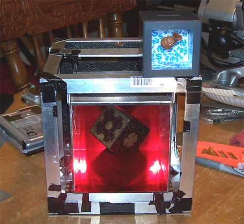
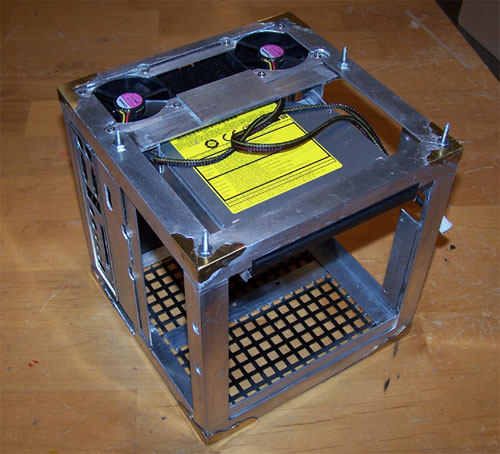
Below is a picture showing one of the banks that this mod is based on sitting atop the mod in progress. Notice how tightly the illusion section fits in beneath the CD-ROM tray, when I am completely finished I will take some pictures to highlight the extremely close tolerances within the case.
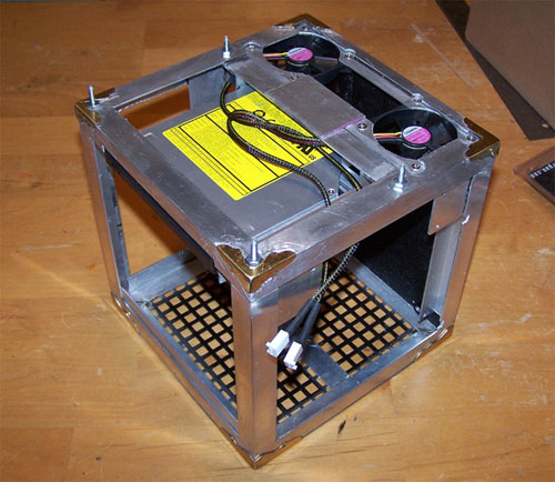
I have been busy at it the last couple of days, below shows the final test fit of the parts ready for install. The deisgn has been simplified and any Alum-Angle pieces that do not absolutely have to be attached to the frame have been removed to allow easier parts access... it all fits toight like a toiger.
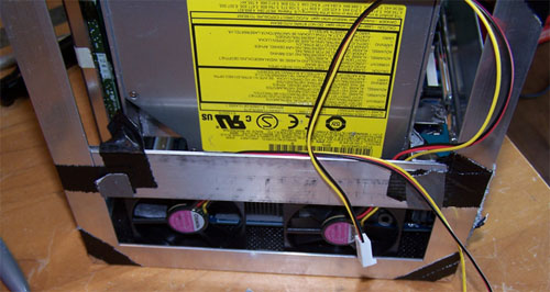
The picture below shows the LCD positioned and ready for final install, it also shows the two 60mm fans placed below the CD ROM tray awaiting some form of mounting method.
The following picture more clearly shows the fan placement, but still not mounted...
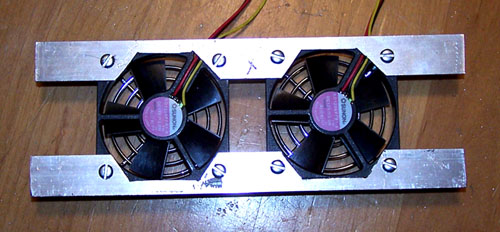
So, here is what I came up with...
Here they are as they will sit when finished, the cut-outs for the fans are not perfect but I will fix that before the final install, for now I am more interested in being sure it all fits together.
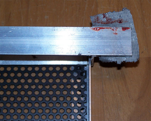
Mod it Til it... um, yeah. The damned thing bit me, fresh cut Alum-Angle is sharp and I did not even notice until I saw this...
I drilled out all the mounting holes for both hard drives, they will be attached using the screw holes on the undersides of the drives...
Finally a test fit of HDD placement, the drives shown below are just dummy drives being used to test fit and will not be used in the mod. Everything has been test fit and all the cutting and drilling to the frame is finished, just a small bit of filing and I can begin J-B'ing the sections together... I might just make my self imposed weekend deadline, which is good because the Duct tape is really starting to wear out.
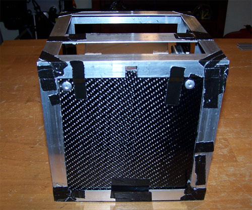
The cool part/bad thing about this mod is that everything sits so tightly next to everything else, when it is completely assembled you can't fit a fart in between some of the components. The space limitations were made evident when I mounted the Matrix Orbital, both HDD's, the MB tray and 6" LCD... not a lot of play. I disassembled the entire thing, removed all the duct tape and began sanding and filing the pieces that mate up in preperation for bonding them together with JB Quick.
After sanding and filing the peces were cleaned with Laquer thinner to remove any dirt or oils and then JB welded together. Below shows the base assembled.
After the base I started JB welding in the corner supports, the blocks are there to help me keep everything square for the four minutes that the JB Quick takes to set up.
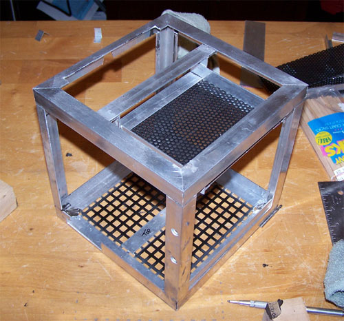
All the corner braces are installed and it is finally tarting to shape up and look like something...
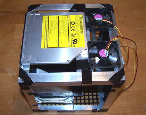
Next I mounted the slim CD-ROM tray to the top Alum Angle pieces for the mod and then attached the whole thing onto the corner braces, as shown below.
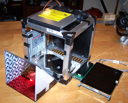
Another test fit of the illusion section...
I mount the Matrix Orbital and the 6" LCD in their final position in the side... looking good so far.
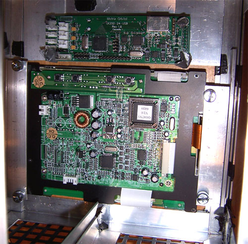
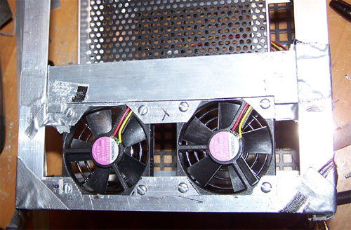
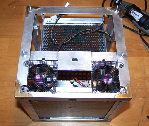
Below shows the back of the mod where all the mainboard connections are and where the second hard drive will be mounted. It also shows a mistake... the top fans are too close together to allow an IDE or power cable onto the CD-ROM drive, not a big a deal as I already have a plan to fix it.
Below is the fix... move the fans as close to the edges as possible without interfering with any other components, doing so required the removal of the fan grills from the inside of the mod, goodbye to dead weight any way.
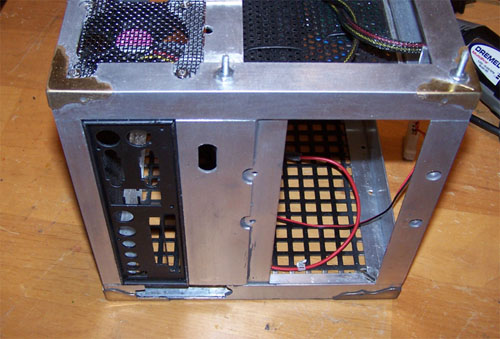
The slim CD-ROM had to be elevated, the power connector for the CD drive sat smack dab inside the fan for the processor and it would have prevent it from working at all, the fix is shown below... elevate the drive and cut into the frame equates to problem solved.
I drilled some holes in the top for four screws that will hold the top on and added decorative brass corners to the mod. The brass corners will not be seen in the final mod, as such they're not being used decoratively they instead provide an extra level of structural support to the framing.
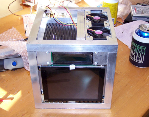
A friend from work that has been following the work log mentioned that I have not been including enough shots of the mod in the log, so to make him happy here is the LCD/M.O. side of the mod...
Next, the back of the mod... all the cables for the mod will reside on this side, I also cut out for the power connector. I am considering putting the power and reset switch on this side as well, I will make my final switch location decision when the switches I ordered from allelectronics.com arrive.
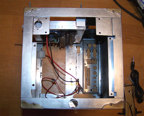
Below is the view from the back of the motherboard tray, also notice that I sleeved the cables to the 60mm fans... totally decent sleeve job, they look sweet.
Lastly a shot of the bottom showing the underside of the CD-ROM tray... this is where the home grown lighting for the mod will reside.
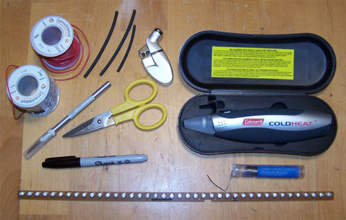
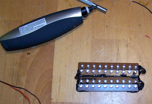
Time to make some lighting, below shows most of the tools and materials used. Wire, heat shrink tubing, soldering iron and solder, X-Acto knife, electricians scissors, Sharpie marker and drum roll please... a 40 LED red automotive brake light strip.
I am skipping a bunch of steps as far as pictures go, but it is all really simple. First I divided the brake strip into fourths and marked it with a Sharpie, next I broke out the dremel and cut the strip into 4 equal pieces. Using the X-Acto knife I scraped back the traces at the cut edges to expose the copper lines and soldered a short piece of wire to each one. Once one section was wired up I connected it to the next, and so on until it was done. The back side of the lighting was given a nice thick coating of liquid electrical tape and was left to sit and dry.
Test firing the lights, I spot soldered a wired four pin molex connector to the backside of the lights and plugged it into my test PSU to make sure that they worked before moving on to the next part...
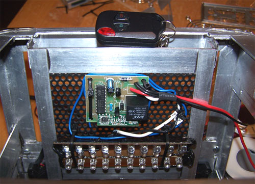
I bought a Logisys remote from Xoxide, it was supposed to come with 2 remotes but mine only had one... but that is ok, I only need one. I removed the PCB from the black plastic casing, wired it to the lights and zip tied the whole shebang to the underside of the CD-ROM tray.
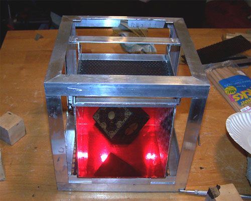
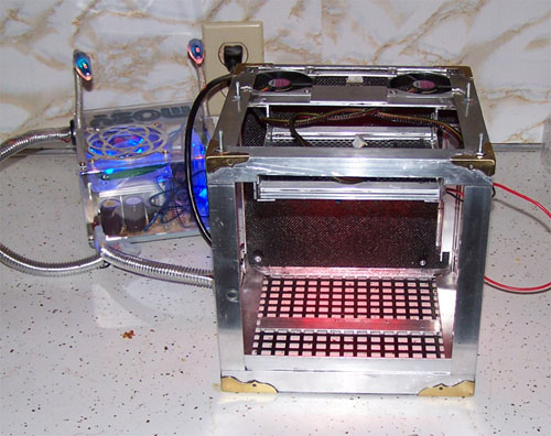
Time for the final test fire, the picture below was taken with the camera flash on and does not show how bright the 40 LED's actually are...
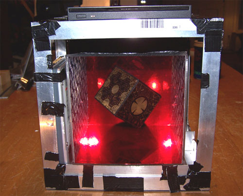
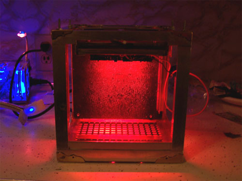
The flash off shot below shows the lighting effect a little better... the lights point directly toward the location of the motherboard and TV tuner card and give off a creepy red glow.
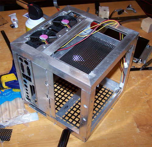
I ordered some speaker grills from
AllElectronics.com and cut them to fit over top of the fans, they didn't have
to be perfect since they won't really be seen, but they came out well.
I also spray painted the motherboard device panel piece black, I still have to polish it up but that will have to wait until I am closer to throwing hardware.
Below is the 6" LCD/Matrix Orbital side of the mod, I cut (with a nibbler) and filed a hole in the upper left corner and another at the center of the bottom, filing circles by eye is not easy (sucks actually), but as you can see they are pretty round.
|
|
|