I already have the parts
layout and basic build set in my head, I could even forego using Sketchup and
just start building it... of course if I did that then how would anyone know
if the finished mod looked anything like my original design idea? I'll
work on throwing down a quick sketch or two of what I'm planning before I
begin so that there can be a final comparative... ok, done. The
following sketch shows my basic plan...
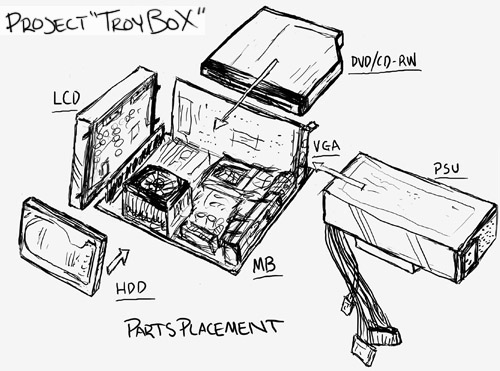
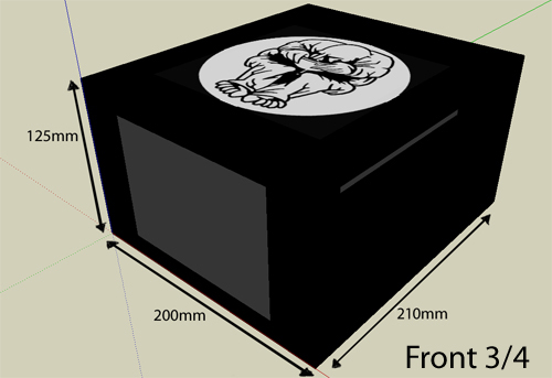
Here are a couple Google
Sketchup renders of the exterior, they are quickies but they should help to
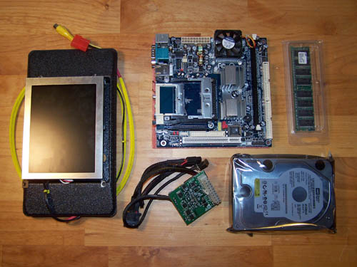
get the basic idea across. In the picture below the 6" LCD is right
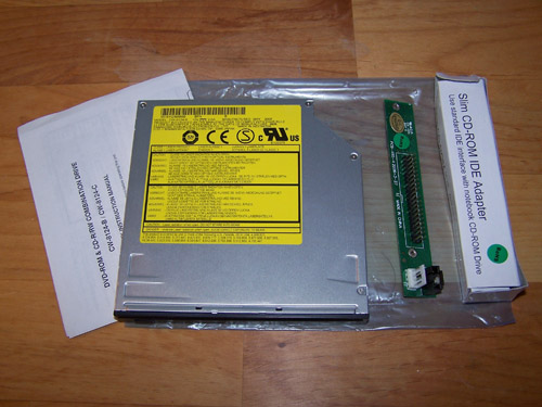
up front and the slot load DVD/CDRW combo drive is on the side. Since I
have a piece of custom etched acrylic I'll be adding a backlit gluttony logo
to the top of this build.
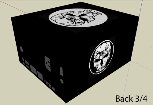
Next up is the view from the
back, everything will port out on this side, the power button will also be
located on the back. The gluttony logo on the side will be a mirrored
80mm acrylic fan grill that will be used to spruce up the side panel where the
video card fans vent hole will be located.
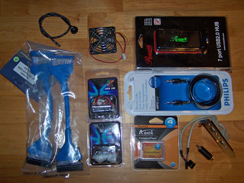
Before I start building here
are a few more pieces of the puzzle... from the top left going clockwise in
the picture below. A wired and sleeved SPST momentary switch that will
be used as the power button, next to it a small fan that will be worked into
the back. Top right corner is a 7 port hub and below it is the audio
cable that will connect to my 46" LCD and in the bottom corner is a two
port USB header and a male to male S-video to RCA adapter. Across the
bottom is a 4GB CF card, two white lazer LED's and two blue 10" rounded
ATA cables.
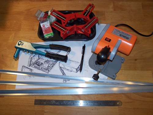
09/07/08 Update...
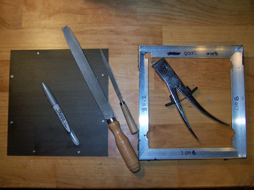
Below is my pop riveter,
assorted rivets and a couple of corner clamps inside a plastic microwave cupcake
pan (best small parts separator/cupcakes ever). A small chop saw, some
Alum Angle, my pencil and ruler round things out.
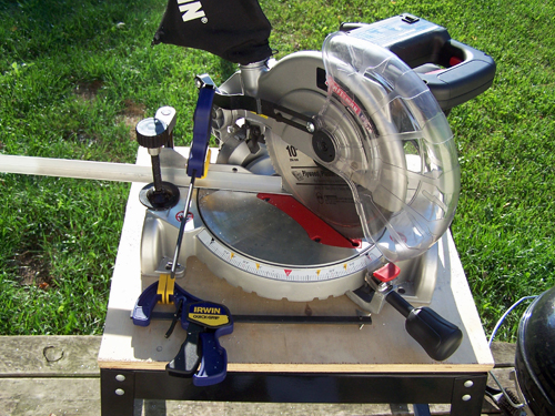
The small chop saw is too
small for the 3/4" outer Alum Angle pieces so I broke out the big gun, a 10"
compound miter saw... it made quick work of cutting the aluminum, all the
pieces needed to frame the outside were cut. I'll use the small chop saw for
the skinnier 1/2" internal Alum Angle pieces and maybe even break out the
Dremel and nibbler for the finer detailing.
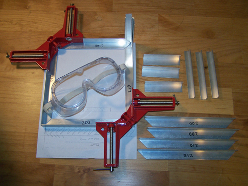
The following picture shows
the (necessary) safety glasses I used when cutting the Alum Angle and it also shows the
bottom of the case framed out using the corner clamps. I am so far using
the same basic design as I did for Hell's Illusion, but it's smaller and I'm
using rivets instead of JB-quick to hold it all together this time. All of the outer
cut pieces still require some serious hand filing to remove any burrs and to size everything up
proper.
09/11/08 Update...
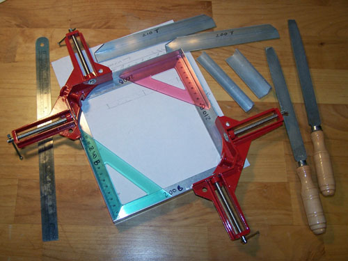
For the last project I
broke out the table sander to make quick work of sizing the cut Alum Angle,
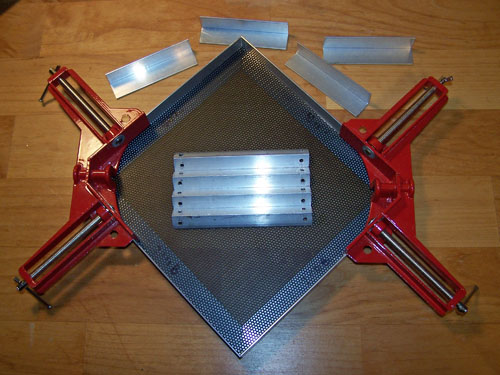
this time I just filed like crazy. In the picture below you can see that
the pieces are sized up and they fit together well, I used a couple of
drafting triangles in the corners just to be sure.
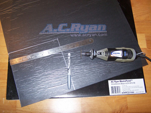
I had some AC Ryan MeshX
that I didn't use for the last project, I measured and marked out the section
to cut with a silver Sharpie, fired up my Dremel and set about cutting the
bottom panel/motherboard tray out of the MeshX.
The picture below shows the bottom panel
dry fit, right before it got too dark to see outside I also finished drilling
four holes into each of the inside corner edge pieces for the rivets.
Tomorrow I plan to buy a bunch of 1/8" nuts and bolts, they will be used
during the fitting stages, once the cutting and fitting together of all the
Alum Angle pieces is finalized they will be replaced by rivets.
09/14/08 Update...
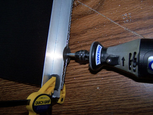
The MeshX
was a little too big and the sides I had cut weren't perfectly straight
anyway, so I used a piece of Alum Angle clamped tight to it as a straight edge
and trimmed up both sides.
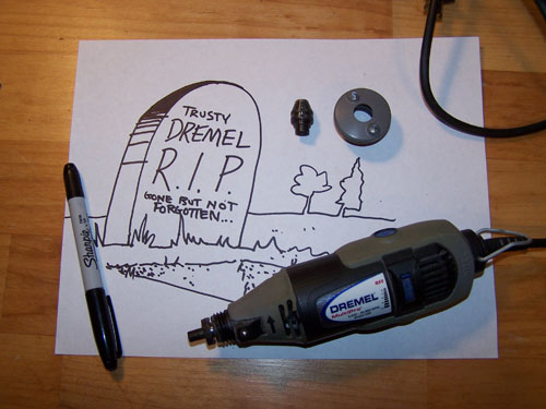
The Dremel got really hot, I
let it cool down and then went to turn it on again and got nothing... it was
dead. I removed the speed chuck and LED light attachment, gave a quick
eulogy and then buried its lifeless corpse in the trash.
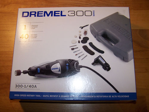
No time to mourn, crying is
for pansies. Looking to get over my loss as quickly as possible I went
to the hardware store and bought a new one... $59 later and it's like nothing
bad even happened, totally back in business.
I used a silver Sharpie to
mark out the spots to be drilled onto the MeshX bottom panel, I also used a
nibbler and files to notch out the Alum Angle where the motherboard stand offs
will be located.
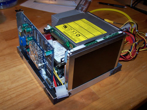
I freaking jammed
today. I started out by stacking all the components up inside the bottom
framework just to see if everything was going to fit... it's really tight but
it all does.
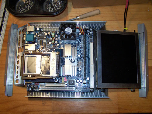
The following picture shows
the bottom Alum Angle pieces that need to be altered to allow the motherboard
back plate and LCD to fit. I drilled the holes in the MeshX for the main
board stand offs and also for connecting the MeshX to the Alum Angle.
I cut the Alum Angle for the
main board back plate first, I used a nibbler so that the lines would be
straight, what a pain in the ass... pain in the forearm and hand is more like it, I wore a
glove to help keep the bruising to a minimum.
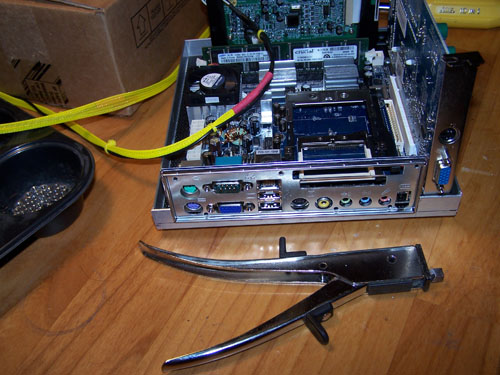
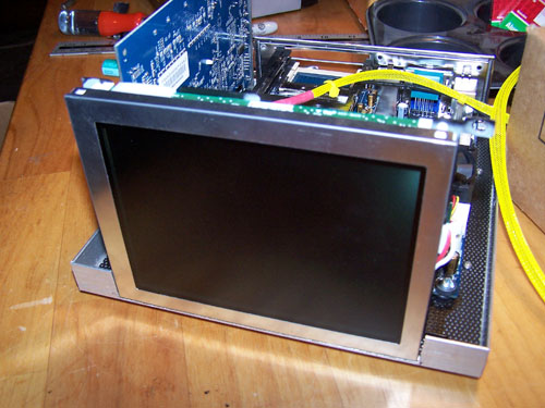
I also nibbled out the
bottom Alum Angle for the 6" LCD and then set it in to test fit, there is
a little left right play so it isn't a tight fit, but that's a good thing for
later on.
Project 'TroyBoX'
- Mini ITX HTPC Mod - Page 2