|
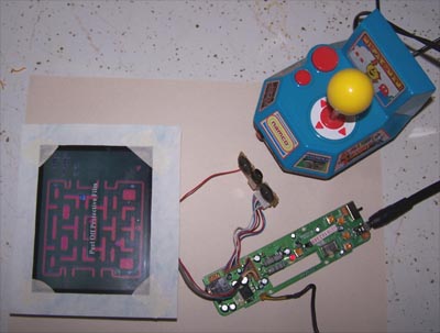
No sense in destroying a perfectly good mouse pad if the screen doesn't work so I wired it up and then fired it up... the picture below shows that it works beautifully.
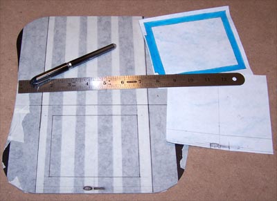
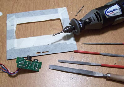
Steelpad4S, you served me well as a mouse pad but the time has finally come for you to suck Dremel and die... I mean that in a good way. Next step is to mask the mouse pad off, measure it up and mark down lines for cutting.
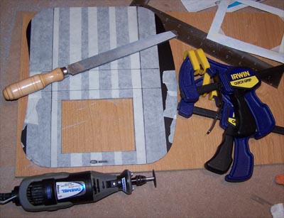
I cut the inside edges that sit next to the screen first, it's easier to do while the piece is whole rather than cutting the outside edges first and then fumbling with it, besides it allows you to keep your fingers further away from the rotary tool which is always good. I also filed off the inside edges up to the marked lines, then cut the outside lines and filed those edges as well.
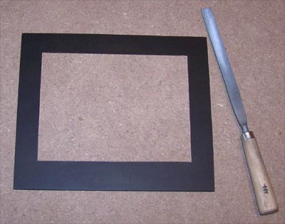
I still have a little fine tuning to do with a file but it's looking good so far (see picture below) and I could almost leave it as is... almost. I'm going to cut the power and brightness controls into the bottom of the faceplate, it isn't in any way necessary for this mod to work, the controls could just as well be hidden behind it all. When the power button is left in the on position the screen will only power up when a signal is present anyway, but the front mounted controls (however unnecessary) will look cool.
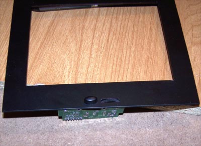
I masked the face plate off again, front and back, then measured and marked the location of the power button and brightness dial onto it. I carefully drilled out as much material as I could with the Dremel and then started filing away, testing for fit as I went.
Below shows the final test fit, not too shabby. I used a marker to color in the bare aluminum edges around the button and dial as well as the rest of the face plate edges, paint will be used as a more permanent solution later.
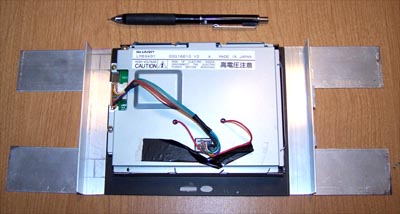
With the face plate made it is time to figure a way to mount the LCD into the PC, for this I used Alum-Angle. I marked the shape of the LCD onto the Alum-Angle in preparation for cutting.
I used a nibbler to cut the side pieces to shape and then filed everything smooth, I also nibbled and file rounded the forward edges of the mounting tabs.
I measured out the best spots to connect the pieces together then drilled holes in the side pieces, traced the pattern onto the mounting tabs and drilled them out, I then rivet the parts together.
Below is a close up of one side of the riveting... it's actually both riveting and exciting.
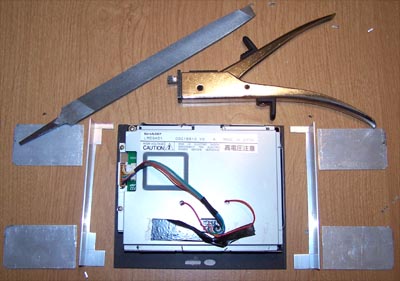
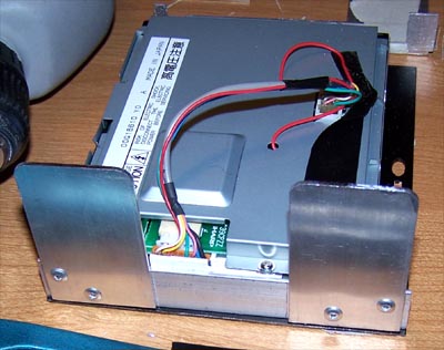
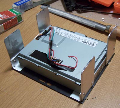
Both of the mounting brackets are finished and shown below in their final test fit, all that is left now is to connect everything together.
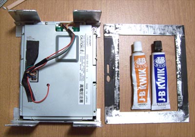
I used J-B Kwik to hold the Alum-Angle sides onto the edges of the screen and then roughened up the backside of the faceplate in prep for attaching the LCD.
I mixed up some J-B Kwik and applied it around the edges of the faceplate, then carefully positioned the LCD on top of it. Next up is mounting the power button/brightness wheel PCB to the back of the face plate.
I used a piece of corner Alum-angle cut to fit, scuffed up and J-B Kwik'ed to the back of the face plate, the bottom corner edges of the PCB will sit on top of the Alum-angle. I cut two pieces of flat Alum-angle to fit the shape of the outside edges of the PCB and two more pieces to hold it all in place.
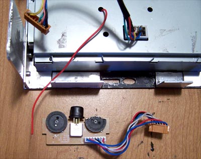
Before I can mount the controls I first have to fix them, early on in the mod the wire that goes from the back of the LCD to the PCB for the brightness wheel had broken off.
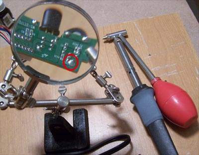
No big deal, the glob of solder circled in red needs to be removed before I can reattach the wiring... the $11 de-soldering iron shown below made short work of it
|
|
|