|
Projects | Guides | Gallery | Articles | Contact Project RYC: Recycle Your Computer by Bewize It's a pity that we have garbage containers for glass, paper and organic materials, but not for computers. So the only way to solve the problem is by your own strength: reinstall Windows and/or make an upgrade. ProModz studio which always aims at innovation and interesting tendencies decided to help those emotional users and created the Recycle Your Computer project. P.S. Special thanks to Y@m@k@si for such a brilliant idea and for help with hardware. Stage1. Idea, Sketches, Stuff
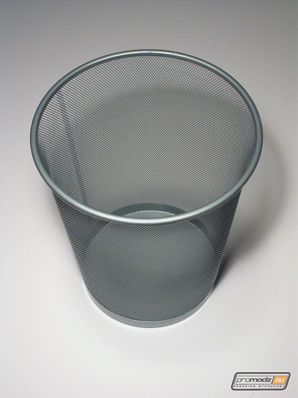
The idea of the project is to pack all the hardware inside of this trash bin. Available space inside is to put it mildly "limited", so the only possible way to place all the hardware is to put it in several "levels". But even then not any mobo will fit inside because diameter of the level that is assigned for it is about 23cm (9"). To be specific the only type of mobo we could use is mini-ITX. We didn't want to use VIA Epia because of its lack of perfomance and expandability. So we chose an Insight P4-ITX mobo. It combines small size and good expandability. We could use a fast P4 CPU (up to 3.06 GHz) and a PCI slot, where a Radeon 9200 was planned to be installed, because the integrated video interface was not convenient to us. Once we dealt with the stumbling block which was the mobo it was the right time to work out all the levels. We wanted to build it up so that it would be as easy as possible to manage with hardware at any time.
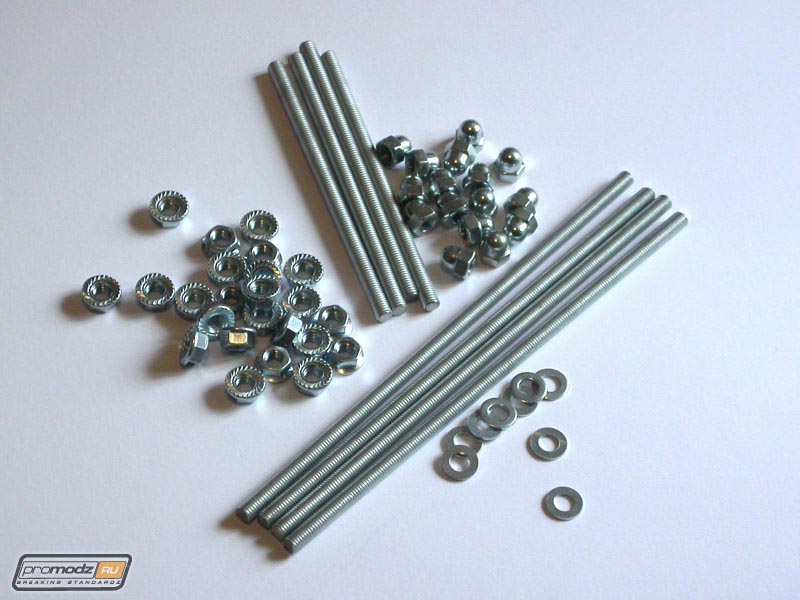
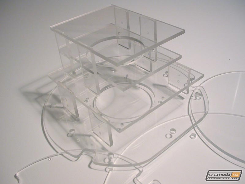
You can see by the sketch above that we have 4 levels here that are joined by tacks 8mm (1/3") thick (shown below).
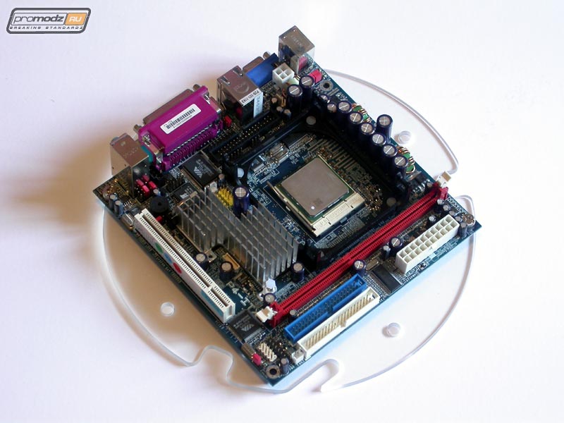
The first level - the bottom one. It is at the left of the sketch. It's as simple as brick - 4 holes for tacks and PSU. The second level - mobo and video. Above and below there is some extra space for PSU wires that will go to the upper levels. On the left and right there are grooves for vertical red neon lights. Also there are 4 holes for tacks.
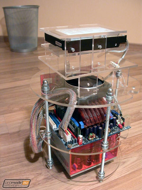
On the third level you can see 8 holes instead of 4. This is the place where the 4 bottom levels tacks end and the other 4 for top levels begin. Again some extra space is left below for wires. On this level we have a bookshelf for 5.25" and 3.5" devices that is detailed in the right bottom corner of the sketch.
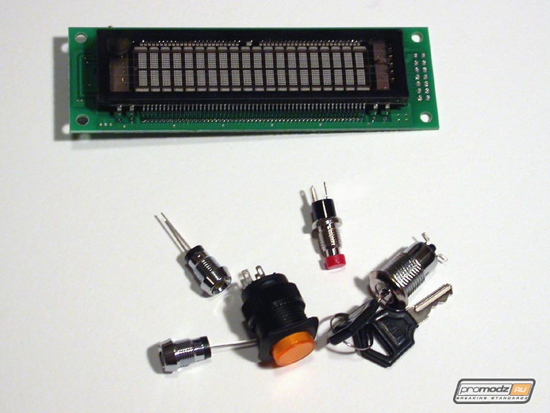
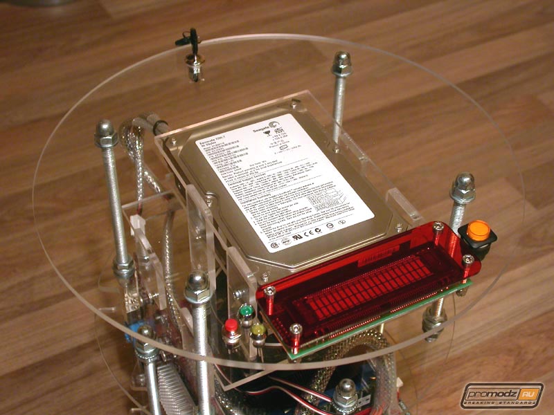
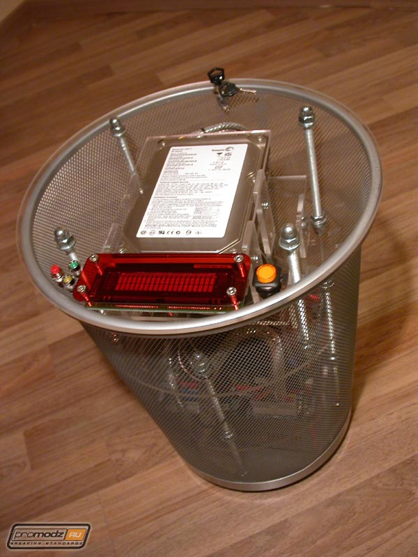
On the top plexi "pancake" we placed the VFD that is covered with red plexi so the color of characters on the display is red-orange instead of light-green. On the right of the display you can see holes for 2 LEDs and RESET button, on the left - POWER button.
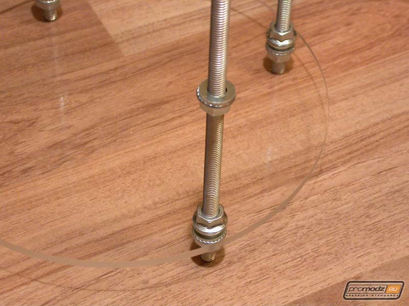
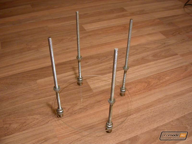
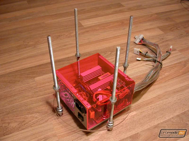
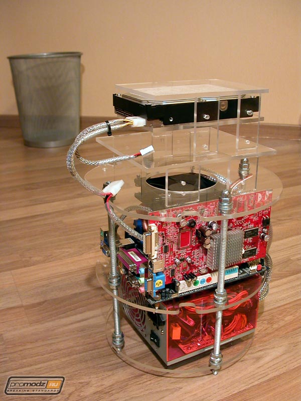
Next stage is first trial assembly of the stuff inside the trash bin. Stage 2. Theory testing / First assembling. Having almost all of the necessary system components ready we decided to accomplish a first test assemble. It's nothing special to tell ... you better look at the photos. They will be accompanied by brief comments and criticism of practice that didn't go well with theory. It happens because of inaccuracy of measurements or simple miscalculation. But I can say this, the mistakes weren't fatal and didn't make too big a problem for us while assembling the system. They just affected the usage comfort negatively. Just a little. ;) Bottom level. On the bottom end of the tacks there're crew-nuts winded. They hold the plexi circle so that when you pull the system out of the bin the PSU won't stay inside and it will be taken out with other hardware all together. While using screw-nuts we sacrificed 5mm (1/5") of space at the bottom.
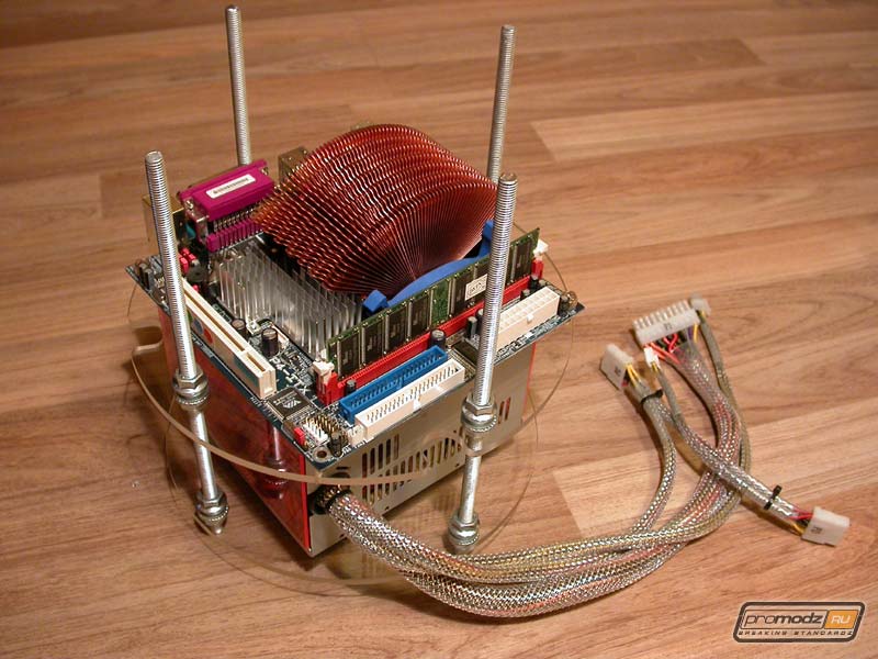
The next level lays directly on the PSU. The mobo is fixed on this level with legs (?). Its actually fixed on two of them by diagonal. Other two are simply supports. This happened because of miscalculation and only 2 of 4 holes were fine, the other two didn't hit the holes in the mobo. Measurements should be taken more carefully.
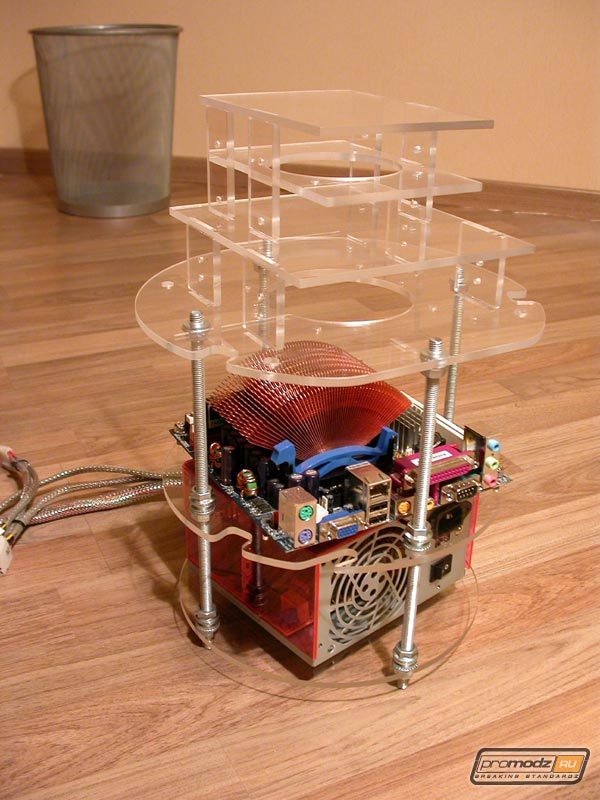
Third "floor" is above the previous one with just enough space needed to install a PCI video-card: about 12cm (5"). This is enough to place a fan over the Zalman radiator so that air would flow free and it won’t produce too much noise. As you may have already noticed the bottom tacks end at this level. It made so the CD-ROM will be able to extend it’s tray.
The main mistake is hidden exactly between the second and the third levels. While projecting every exact level based on common sense and then after assembling them altogether we find out that our common sense let us down. General things don’t follow the exact ones, so after assembling we find the project had some defects which were not noticeable before we had all the parts in our hands. For example, wires from PSU from the first level pass to the second near one side of the mobo, and it passes to the third level on the other side. Plus, the wires do not make too straight a way to the HDD and CD-ROM and their length is hardly enough. It is not a big problem btw, but it is unpleasant.
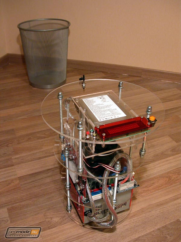
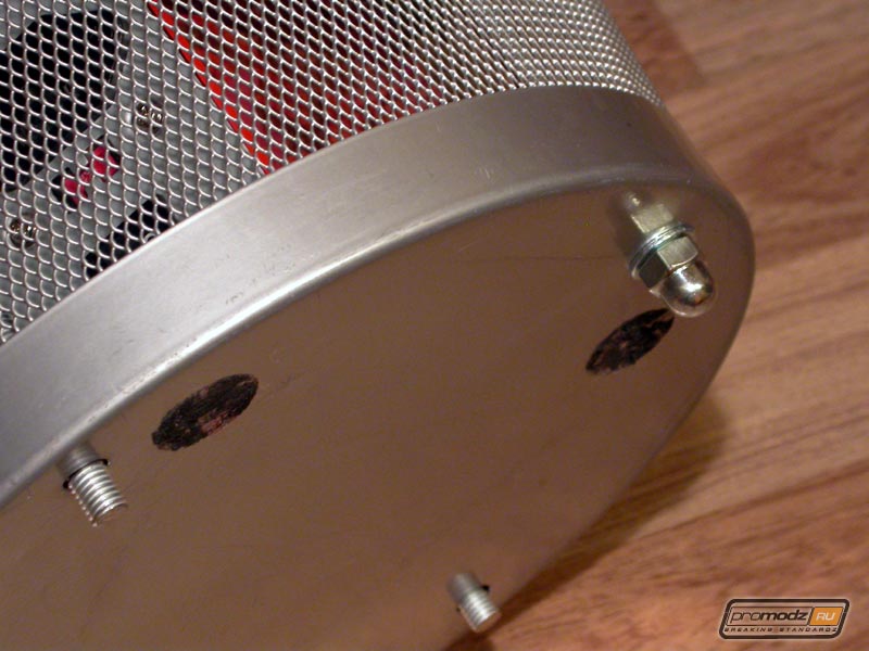
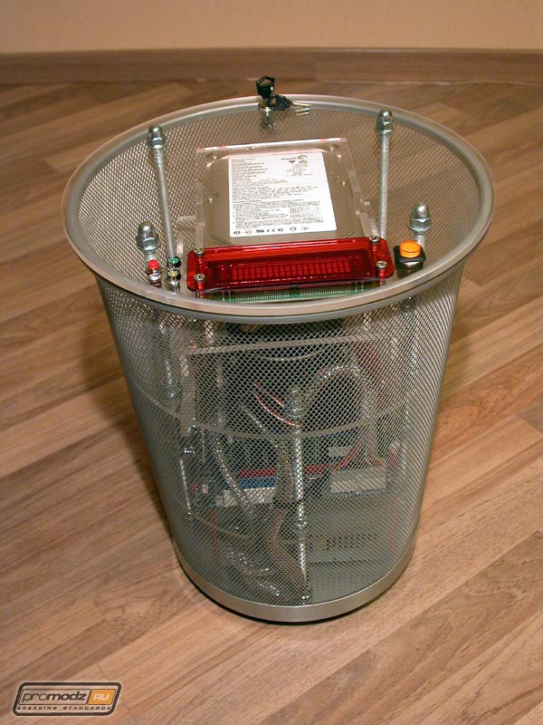
After installing plexi on the top level it is the right time to insert our "book-stand" inside the bin. For fixing it to the bin there’re 4 holes in it’s bottom which hold our 4 tacks with screw-nuts that work as 4 case feet now.
Our bin looks awesome after assembling. Sure, we don’t have drives, rheobus, CCFL’s and some wires, but our main idea is clear. We have to cut holes in the grid of the bin for access to devices, sockets and buttons. As a whole we can confidently say that 50% of the work is done... stay tuned.
|
|
|
