|
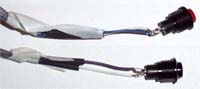
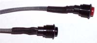
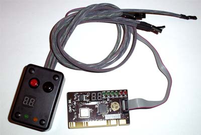
Since I decided to change out the power and reset switches it was time to remove the old switches, break out the soldering iron and heat shrink tubing and put it back together, the second picture shows the finished wired and sleeved switches.
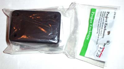
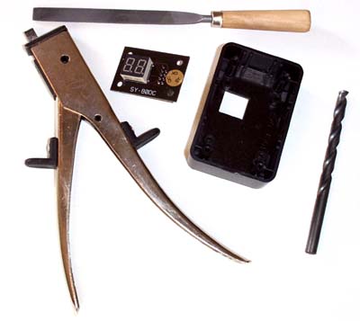
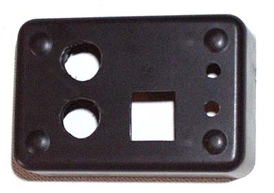
I measured out the placement for the PCI POST card LED breakout and drilled a hole in the project box centered where the LED display would sit, this wasn't easy and I ended up making a paper template of the breakout to make things easier. I then used the nibbler in the drilled hole to remove enough of the plastic so that I could rough file and dry fit the LED readout in the project box. Test for fit then file... over and over until it is right (and tight).
The reason I cut the rectangle for the two digit LED first... well, if it was wrong I could always buy a new project box knowing that I didn't have much vested in the last one, thankfully I got it in one try. I then drilled the holes for the LED's using a 3/16" bit and drilled pilot holes for the switches. I first tried using a 1/2" drill bit to make the switch holes, but it wanted to shred the plastic enclosure and absolutely would not work so I instead used the Dremel with a pointed grinding stone to rough cut the switch holes. I also cut out the section where the wires will come out of the top side of the box using the nibbler, now it's just a matter of filing it all to make things fit correctly.
When everything is filed right and perfect it is time to install everything into the box. I started with the LED's, pushing them into the holes I drilled and securing them in place with hot glue. Next I installed the POST card breakout and speaker, again hot gluing them down. Lastly I installed the power and reset switches, ran the sleeved wires to their cut out and screwed the box together. You can see the finished product in the picture below.
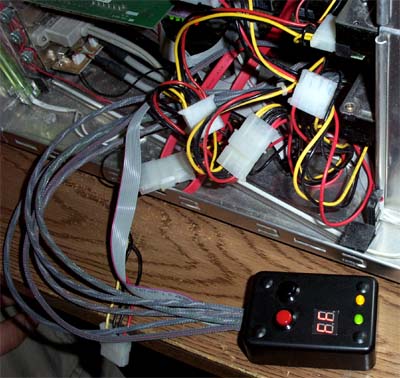
About all that is left now is to test fire it, which I promptly did... the result can be viewed below. The test box performs like a champ, everything needed to test a (newer) PC is incorporated and easily viewable, the box not only shows POST codes but has an audible POST, shows HDD and power via LED's and can also power on or reset the machine without needing the PC case to do it.
|
|