|
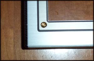
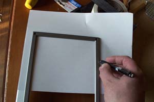
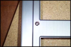
Time to find a center line so that the Lazer LEDs can be mounted onto the top edge of the bezel. As for those tacky looking brass screws... time to say bye bye, take out the top four and slightly loosen the bottom two. Slide a sheet of paper under the front aluminum frame piece and trace the side edges onto the paper.
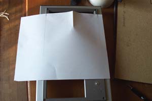
Fold the paper so that the marks you just made line up, the crease you make will be your center line. Slide the paper back under the frame piece, line up the side marks with the edges and transfer the center line to both the frame and the bezel.
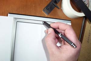
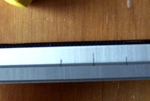
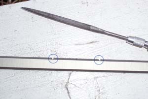
Next, trace the outside edge of the Lazer LED onto the paper and fold it to get it's center line, line the center crease up with the center mark you made onto the bezel and transfer the outer edge lines onto the bezel and frame piece as shown below. Remove the frame and get out the hobby file, the bevel has to be removed where the LEDs will sit for it to be flush along the top edge of the case and the filing you do here will serve as a guide edge for the larger file later.
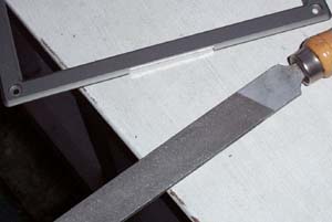
File the bezel bevel level... say that three times fast. Use the large file to carefully remove the bevel inside the cuts, be careful not to file too much material off on the side edges because you want a nice tight fit for the LEDs. Line up the LED unit at the top of the bezel and mark where the screw holes and the LED wiring go. I will not lie... I just eyeballed this part, holding the LED up to the edge I penciled in the marks for the screws and wiring as shown in the picture below.
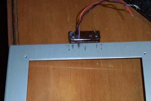
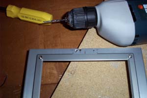
I reattached the frame piece to the bezel using six silver screws that were in my spare computer parts box, the thread of the screws I used was identical to that of those that came with it stock, they are not as noticeable now and they look a lot better than Lian Li's choice of screw. With the front frame section back on I drilled out the holes for the LED's screws and wiring. I then filed out the metal between the top of the bezel and the hole I just drilled for the wiring so that the wires can be slid in and out instead of poked through.
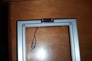
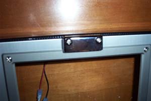
Looking at the left picture below you will notice that I put male 16-14AWG bullet splice disconnects on the wiring from the LEDs, there is also a powered molex pass through modded with female bullet splice disconnects inside the top of the case. I have concluded that it is easier to disconnect the wiring rather than having to completely remove the LEDs every time the front bezel needed to be removed. The second picture shows how nicely the LED unit lines up with the freshly filed bottom section and also with the top of the bezel.
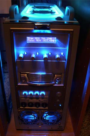
And finally a gratuitous shot of the "new" front of my case, it looks good as ever and honestly I like it better than the original. Sadly this marks the end of mods for MOBY, sometimes something like destroying and having to re-mod a bezel has to happen to make you realize that enough is enough everything has to end somewhere. Project over-mod is over, MOBY is done. And I'm not just saying that because my new case is sitting on the floor next to me... ok, maybe I am.
I had a tall cold beer and smoked a fine cigar after I finished the above explained mods, I can honestly think of no better way to congratulate yourself upon their completion should you decide to try these mods out on your own Lian-Li . Happy Modding Guide written by Troy, aka ARTbyTROY. |
|
Disclaimer: This how-to guide is presented for informative purposes only. CaseModGod.com can not and will not be held responsible for damages to or resulting from anything that you may decide to do to your case or hardware and also can not and will not be held responsible for injury to your self or others as a result of attempting any of the things that are shown on this site. Basically you are responsible for your own actions whether said actions were based on information garnered from this site or elsewhere, learn to deal with it. |